dinsdag 23 mei 2017
maandag 22 mei 2017
zondag 21 mei 2017
DIY 3D & Nest
We first made the DIY model in 3D. Then we converted it to 2D. to make maximal use of the wooden plates we organized the 2d planes so there is a minimal waste of wood.
Small plate:
Big Plate:
Handle:
These are the nest plans we used for the laser cutter.
Small plate:
Big Plate:
Handle:
These are the nest plans we used for the laser cutter.
Big plate and small plate.
Two small plates and handle.
two small plates and second part of the previous 2 plates.
woensdag 10 mei 2017
Consult 9/5
try to design the injection molded part without the undercut. By changing the lock system to the outside. Use the injection molding script to simulate the part in NX. the handle part can be a solid piece.
For the middel production we use the sheet metal production. It is better to use round form for ponsing. also use the part for the handle.
The diy content is good. no problem to use standard components.
CES: used ABS is oke, try to compare with PP and PE reinforced with fiberglass.
dinsdag 9 mei 2017
Material Injection Molding
The material chose for injection molding is: ABS with 30% fibreglass.
The most important factors were the price, Strenght and the compatibility with injection molding.
maandag 8 mei 2017
DIY Cad
These are the basic drawings for de DIY model. The snap-connections still need to be drawn. Then we can proceed to make the Lasercut drawings and make the prototype.
Tool plate:
On the plate we will place the tools. This is the large version. There is also a smaller version which is half the length. (20cm)
The snap-connections will be on the side.
The crosses are 25 mm apart. in these crosses come another part, the sliders. On the sliders we will connect a flexible piece of fabric. This fabric will hold the tool and the Sliders will press the fabric against the back of the plate.
The handle part is a more difficult part so we still need to optimize the design.
vrijdag 5 mei 2017
New injection molding part
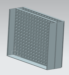
for the injection molding part we started looking at a new design for the shelf. So it would fit into one mold. This would reduce the cost and give a stronger object in the proces.
We came with this solution:
Questions for the consult.
How about the release of the mold? is this possible? thickness has to be changed?
dinsdag 2 mei 2017
Consult 2/5
CAD: mass production
Try to get lose of the Diy idea. The main principle has to be the same but the form of the part can be totaly different.
Now to many stiffness ribs. Maybe try 1 part. Think about the unloading. But better because there is just need to use one mold.
Use of the flexible part. connect with a snap connection. Possible materials: TPE or rubber.
middel production.
What is the max production of the parts? maybe possible as an mass production technique. Use sheet metal method in CAD. easy to unfold. In the 2D sketch you need the unfolded part.
compare price to the injection molding.
Connection part.
The way of holding the tools is ok. Think about the price of some parts. and the standarisation of the connection part.
Mass production injection molding
For the mass production part. We want to use injection molding. Therefore we will use an triangle part to keep the parts together.
Middel production sheet metal part CAD
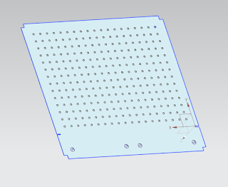
For the middel production we will use a sheet metal to deform the L part . In the next images you see the unfolded part of the sheet metal.
The folded part and the handle part will follow later on.
Connection parts
Use of a T-form connection piece. To connect the tools on the board.
option two. Use a metal connection piece to center the material on the board. This will hold the tools together. But it is a more standard part.
maandag 1 mei 2017
DIY Lasercut
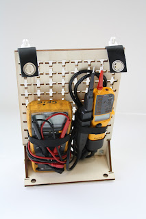
This is the finial idea for the diy
prototype.
We made hand sketches, after that our idea is good
enough we will make a CAD design and proceed to make the lasercutdrawings.
Plate:
The main idea is still the same. There is a back plate
and a bottom plate. Made out of 4mm multiplex wood. These two pieces will slide
into each other by a shape connection.
To support the who pieces there will be two side
triangular shaped pieces.
These triangular shapes will be connected to the
back and bottom plate via snap-connections.
These connections however are on the back and
bottom plate itself so there is no direct stress for the weight on to them.
On the back plate there are cross cut-outs. these
crosses have a larger square cut-out in the center.
To attach the tools we make use of a U connection
with thicker end on the arms of the U. these U shapes fit in the cross center
and can by sliding to any of the four directions so it is stuck.
On one of the U shapes there will be a loop with elastic
fabric.
And the other side of the tool there also will be a
U shape but the elastic fabric will be sandwiched between the U shape and the
back plate. This way On side can be removed to take of the tool.
The functionality between the plates also remain
the same. we will use Conner pieces on the back to slide them into each other.
On the top there will also be mirrored connections
and on the front side there will be leather fabric with hollow rivets. The Leather fabric will be on the top side of the plate.
Handle:
We made the handle a lot smaller than the previous
model. the holes will be asymmetrical. so the plates can be closer to each
other.
In the center there is a reinforcement bar to make
sure the handle his strong enough.
To be able to attach the plates we make a sliding
bar with holes so the cornerpieces on the back of the plates can be fitted into
these.
Abonneren op:
Reacties (Atom)


